Document Type : Original Research Article
Authors
1 Department of Materials Engineering, School of Engineering, Yasouj University, Yasouj, Iran
2 Department of Materials Science and Engineering, School of Engineering, Shiraz University, Shiraz, Iran
Abstract
Zn based composite coatings reinforced with TiO2 nanoparticles were fabricated via electrodeposition with 5, 10, and 15 g/L TiO2 concentration under variant current densities of 0.08, 0.1 and 0.12 A/cm2. Field emission scanning electron microscopy (FESEM), energy dispersive spectroscopy (EDS), x-ray diffraction analysis (XRD), weight loss measurements, salt spray technique, anodic polarization, and eventually potentiodynamic polarization tests were conducted and the corresponding findings were discussed. Rising the electrodeposition current density from 0.08 to 0.12 A/cm2 for both pure Zn and Zn-TiO2 coatings led to deposit more and smaller crystals and with incorporation of TiO2 nanoparticles, the morphology changed from hexagonal crystals to flake type grains. Increasing the TiO2 concentration from 5 to 15 g/L, steadily lowered the TiO2 incorporate rate (vol.%). Accordingly, the same smoothness and even more uniformity with smaller crystallites was observed at 15 g/L compared to that of 5 g/L. Weight loss measurements, salt spray tests and anodic polarization test showed remarkable superior corrosion resistance of Zn-TiO2 (5 g/L) than that of pure Zn coating. An increas in icorr (µA/cm2) from 0.08 to 0.1 A/cm2 occurred, followed by a decrease from 0.1 to 0.12 A/cm2 for pure zinc coating. By increasing the current density from 0.08 to 0.12 A/cm2 for Zn-TiO2 coating, a steadily decrease of icorr was observed. Furthermore, by rise of TiO2 (%C) from 5 to 15 g/L, icorr experienced a significance increase that could be ascribed to the remarkable reduction in TiO2 vol.%. Ultimately, the optimum corrosion resistance belonged to the electrodeposited Zn-TiO2 (5 g/L) coating deposited 0.12 A/cm2 exhibiting the lowest amount of icorr of 2.7 µA/cm2 equal to 1.6 mpy.
Graphical Abstract
)
Keywords
Main Subjects
Introduction
In recent decades, zinc has been widely applied as a well-known coating on the steel surface to enhance its corrosion resistance. The application of zinc coating on steel surface is performed through electrolysis or galvanization. Given that zinc is a metal with higher activity (more negative electrochemical potential) compared to steel, thus zinc must be protected to increase the service life of coating as well as steel [1]. Due to high corrosion rate of zinc coating in very strong and aggressive acidic or alkaline environments, they are normally used in the pH range of 6-12. Moreover, zinc coatings are too fragile to be applied in harsh corrosive environments like those containing pollutants produced in various industries [2]. Remarkable properties of employing chromate conversion coating on zinc evoked interest among researchers in recent years [1]. Having said that, chromate coatings are unstable at temperatures higher than 70 C. Moreover, during the production of chromate, coatings concerns arise due to the formation of white rust. To be more specific, white rust formation can be mitigated for a limited time while the deposition of chromate conversion coating occurs. Although, this process has been recently kept away from application due to environmental hazards [3]. Today, eco-friendly materials have attained increasingly attention and investigation on the metal matrix composite coatings has been going on for a long time. In recent years, targeted environmental plans have led to remove chromium based coatings and fabricated new eco-friendly composite coatings with the assistance of nanotechnology resulting in new developments in nanocomposite coatings [4,5].
Applying corrosion inhibitors is regarded as another strategy to increase the service life of the zinc coated materials to modify their surface behavior [6]. Most of the inhibitors are organic compounds containing nitrogen, sulfur and/or oxygen elements. Compounds with functional groups containing hetero-atoms, highly promote the corrosion inhibition. In general, these compounds are adsorbed on metal surface and block the active sites of corrosion [7] and provide a barrier between corrosion medium and metal. As a result, the interaction between metal atom and environment will be reduced and the formation of white rust will be also controlled.
However, the chromium ions and organic inhibitors are liberated to the environment as the corrosion occurs. These compounds are toxic in nature and produces pollution and serious health hazards. What is more, in severe corrosive medium, the protective layer gets damaged as the result of severe corrosion. One of the most important difficulties, here, is the method for application of chrome passivation due to requiring expert skills [8].
Thus, one of the most increasingly interested solution to modify zinc coating and other metal-based coating properties is to introduce second phase reinforced particles into the base metal matrix and create a composite coating. Fabrication of composite coatings has been widely employed as a highly useful approach where ceramic, oxide, and also polymeric micro-particles or nano-particles are co-deposited on the metal surface using suitable electrolyte. These composites have a wide range of properties such as dispersion hardening, self-lubricity, high temperature inertness, good wear and corrosion resistance, and chemical and biological compatibility [5, 9-17].
Among the major fabrication techniques to produce metal composite matrix, liquid and solid-state methods cannot be able to manufacture thin films. Furthermore, spray forming or spray deposition technique, and also chemical vapor deposition (CVD) processes can be only performed at high temperatures which is a major disadvantage of these methods.
Thus, electroless plating and electrodeposition can only be applied for fabrication of metal matrix composite (MMC) at ambient temperatures. Since the electrodeposition technique has been utilized to a large extent to fabricate metal matrix composite coatings, it can be chosen as the best alternative for production of metal matrix composite (MMC) coatings [18-24].
The composite coatings are of high significance in recent years, owing to the successful incorporation of nanoparticles in the process of co-deposition by electrolysis. This technique is carried out under a normal pressure and room temperature, and often possesses a high level of deposition rate. Electrodeposition has been well known as one of the most important approaches in order to fabricate nanocrystals and above all nanocomposites, where nano-sized particles such as SiC, TiO2, Al2O3 [25], ZnO [26], WC, PTFE, SiO2, CNTs, CeO2 [27], Ni3S4 [28], MoS2 [29], graphene [14], diamond [30], etc. have been evoked scientific importance in metal matrix composite coatings (particularly in zinc coating), due to their magnificent role on the hardness improvement, self-lubrication, wear and corrosion resistance, and also compatibility in biological and chemical fields [4,15,19,23,31-36].
More importantly, electrodeposited coatings possess unique characteristics namely, high corrosion resistance, self-lubricity, high temperature inertness, and biological compatibility [31,37]. TiO2 possesses also various useful applications in different kinds of industrial and domestic fields such as metallic and organic coatings, catalysis applications as catalyst support, wastewater treatment, and photovoltaic cells. The photocatalytic activity of TiO2 has attracted highly attention in various metallic and organic coatings [38-44], and also in Zn plating on steel has been reported [45,46]. Another important advantage of TiO2 comes from its high ability in reinforcing metallic coatings to greatly enhance the corrosion and wear resistance, hardness, and other mechanical characteristics, and also magnetic properties [47]. There are several research works that made a thorough investigation on the electrodeposition and corrosion characteristics of Zn-TiO2 composite coating [48-51]. However, these studies are limited and there is a need of a comprehensive study on the electrodeposition and microstructure-corrosion resistance relationship.
The main purpose of this research study is to explore and assess the electrodeposition of Zn-TiO2 nanocomposites and their corrosion behavior upon the obtained results from weight loss, salt spray, electrochemical methods (anodic polarization and potentiodynamic polarization), and surface morphology after corrosion process. The relation between surface morphology of electrodeposited coatings, XRD measurements, and corrosion properties were also determined.
Materials and methods
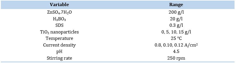
In this study, the pure zinc and Zn-TiO2 nanocomposite coatings specimens were electrolytically deposited in a sulphate bath. The constituents of the bath were 200 g/L ZnSO4, 20 g/L H3BO3 (for keeping pH constant), 0.3 g/L sodium dodecyle sulfate (SDS), and certain content of titanium dioxide (TiO2) nanoparticles possessing a particle size ranging from 40 to 50 nm. Figure 1 displays a schematic presenting the experimental setup utilized for electrodeposition of pure zinc and zinc-nano TiO2 composite coatings.
 Figure 1. Experimental setup of electrodeposition, (1) pulse power supply, (2) plating solution, (3) TiO2 nanoparticles in composite, (4) suspended TiO2 nanoparticles, (5) ions cloud, (6) anode, (7) cathode, (8) magnetic stirrer, and (9) reference electrode.
TiO2 nanopowder was purchased from US Research Nanomaterials and possess anatase phase. The specifications of TiO2 nanopowder are reported in Table 1.
Moreover, SEM micrograph, TEM image, and XRD patterns of the aforementioned nano TiO2 powders are depicted in Figures 2 to 4, respectively.
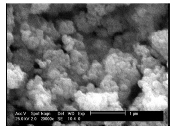
Figure 2. SEM micrograph of TiO2 nano powders.
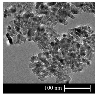
Figure 3. TEM image of TiO2 nano powders
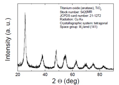
Figure 4. XRD pattern of TiO2 nanoparticles.
Analytical reagents and distilled water were utilized to prepare the plating solution. Before plating occurs, the TiO2 nanoparticles with a mean diameter of 40-50 nm were dispersed in the electrolyte. The nanoparticles were easily agglomerated owing to their high surface energy, followed by controlling the agglomeration owing to the addition of a surfactant like SDS to the bath. The bath was stirred for 24 hours before conducting electrocodeposition experiments. Low carbon steel was chosen as the cathode and anode was zinc (99.96%) which could compensate the consumption of zinc ions according to its sacrificial behavior. The low carbon steel was mechanically polished and degreased with acetone followed by water wash. Dipping in 10% HCl was employed to activate the zinc surface for few seconds, then was water-washed.
The area of anode was 3 times higher than cathode for prevention of anodic polarization. The bath temperature was at room temperature (298 K) and pH of the bath was set at 4.5. The electrodeposition process was carried out under mechanical stirring. Bath composition is indicated in Table 2.
After the electroplating process, specimens were studied by X-ray diffraction (XRD) analysis via a Philips X-pert-pro diffractometer with a copper Kα source. The weight loss measurements were performed for low carbon steel specimens which were coated with pure zinc and Zn-TiO2 nanocomposites. To assess the corrosion behavior of nanocomposite coatings, an equal area of specimens was immersed in NaCl solution (3.5 wt.%) at room temperature. The loss in weight was measured once in every 72 hours for a period of 9 days.
Table 1. Specifications of nano TiO2 powders

Table 2. The solution composition and electrodeposition parameters
After the experiment, the corroded samples were rinsed in H2SO4 15 wt.% solution, dried in hot air, and then the weight loss was noted. The weight loss measured was applied on calculation the corrosion rate. Salt spray test (according to ASTM B117) was also performed in order to make a comparison between the corrosion characteristics of pure zinc and Zn-TiO2 nanocomposite coatings. Specimens were subjected to continuous neutral spray of 5% NaCl vapors. The specimens were investigated carefully and the period for formation of the white rust on coatings was noted. A conventional 3-electrode cell was used for potentiodynamic polarization studies. The pure zinc-coated and Zn-TiO2 nanocomposite coated specimen were employed as working electrode with active surface area of 3 cm2. Saturated calomel electrode (SCE) and graphite were used as reference and counter electrodes, respectively. The potentiodynamic polarization measurements and also anodic polarization curves were drawn to assess the corrosion resistance of coating samples. The electrolyte was 3.5 wt.% NaCl solution for anodic polarization tests and 1M NaCl for potentiodynamic polarization tests. Potentiodynamic polarization tests were carried out via computer controlled the Autolab PGSTAT 302N equipment by the scan rate of 1 mV/s.
The morphology of the deposited specimens was studied before and after corrosion tests via field-emission scanning electron microscopy (FESEM) and the composition of composite coatings was evaluated by energy dispersive spectroscopy (EDS) analysis. The weight percent of both elements Zn and Ti in the composite coating specimens were analyzed by EDS and then volume percentage was calculated using densities of zinc (7.13 g/cm3) and nano TiO2 powder (4.23 g/cm3). It is worth mentioning that the EDS measurements were applied three times and the average amount was reported for each sample.
Results and Discussion
SEM and EDS Analyses
As it is displayed in Figure 1, the FESEM images of deposited zinc coatings are observed in different current densities (0.08, 0.1 and 0.12 A/cm2).
As it is observed in Figure 5, zinc deposits have a hexagonal platelet microstructure [52,53]. According to Figure 5a, one hexagonal crystal of zinc is observed, while the number of these crystals is increased by increasing the current density. To be more specific, applied current acts as the main driving force for ion mobility to cathode surface leading to a higher reduction rate of ions and subsequently smaller and more crystals [52-55]. Figure 6 also shows FE-SEM images of zinc composite coatings are observed in different current densities.
Clearly, by incorporation of TiO2 nanoparticles into the zinc matrix, remarkable grain refinement occurs and the general morphology of zinc converts drastically from a hexagonal platelet state to flake type grains. This proves that increasing the nucleation sites and also grain boundaries cannot be sustained by hexagonal platelet microstructure in zinc metal and results into formation of a highly different morphology of zinc-matrix composites. This kind of grain refinement and reduction in crystal growth is also reported by Zhang et al. [54] and Delacourt et al. [55]. This significant change in morphology will also make different trend in the corrosion behavior of zinc matrix nanocomposite coatings that will be discussed later. By increasing the current density, a rise in applied energy of ions is occurred, and accordingly results into the increased reduction rate of ions. As a result, according to Figures 6a to 6c the number of flakes is growth and their size is reduced indicating that the area of grain boundaries has been increased.
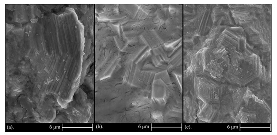
Figure 5. FESEM images of zinc deposited coatings deposited at different current densities: a) 0.08, (b) 0.1, and (c) 0.12 A/cm2.
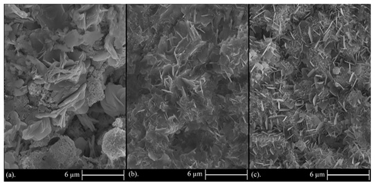
Figure 6. FESEM images of Zn-TiO2 composite coating deposited under current densities of: (a) 0.08 A/cm2, (b) 0.1 A/cm2, and (c) 0.12 A/cm2.
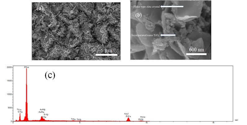
Figure 7. (a and b) FESEM images of Zn-TiO2 (10 g/L) nanocomposite coatings electrodeposited under the current density of 0.12 A/cm2 and (c) EDS measurement.
Regarding the volume percent of incorporated nanoparticles in the composite coating, it should be noted that by rising the current density, the alteration in morphology depends on the volume percentage of nanoparticles participated in the coating. Thus, it can be concluded that the number of participated nanoparticles in the zinc matrix coating has two major influences: (i) reduction in crystallite size and (ii) formation of a more uniform and smoother surface. Figure 6b shows more obvious and smaller flakes and, has a greater number of flakes and also has a smoother and more uniform surface than Figure 6a and 6c. This is due to higher content of incorporated particles in Figure 6b (current density of 0.1 A/cm2). As mentioned, the highest amount of incorporated TiO2 in the nanocomposite coating is related to the sample coated at 0.1 A/cm2 current density. Under the current density of 0.08 A/cm2, Zn 2+ ions have a lower mobility than 0.1 A/cm2 and this results in the lower incorporation of particles into the coating. By enhancing the level of current density to 0.1 A/cm2, the mobility of Zn2+ ions increases and results in more incorporated particles into the coating. However, by further rising the current density to 0.12 A/cm2, the volume percentage of incorporated particles decreases due to the higher mobility of ions than particles. The similar result have been obtained by Stojak et al. [56]. EDS measurements were also applied to confirm the participation of TiO2 nanoparticles in the zinc matrix. These measurements also determine the composition of composite coatings and the amount of participated TiO2 nanoparticles into the zinc matrix. Figure 7 shows the FESEM images and EDS measurement of Zn-TiO2 sample deposited at the concentration of 10 g/L TiO2 nanoparticles and electrodeposited under the current density of 0.12 A/cm2.Figure 8 shows the FESEM images of Zn-TiO2 nanocomposite coatings deposited at variant concentrations of nanoparticles in the solution.
In Figure 8, it is observed that by rising the concentration of dispersed nanoparticles in the electrolyte from 5 to 15 g/L, the content of incorporated TiO2 nanoparticles in the coating was steadily decreased. In spite of the decrement in incorporated particle content in Figure 8 (b and c), the microstructure of these figures has the same smoothness and uniformity as Figure 8a and also there is a more uniform structure with smaller crystallites (see Figure 8c) due to more uniform distribution of TiO2 nanoparticles at the concentration of 10 and 15 g/L, so this can form a more uniform and smoother coating in spite of less incorporated particle content in the coating. These parameters also affect the corrosion behavior which will be discussed later. As mentioned, by increasing the concentration of TiO2 nanoparticles in the electrolyte under a constant current density, the content of incorporated nanoparticles in the coating instantly reduces owing to the lower electrical charge for each nanoparticle according to the constancy of ion concentration in the solution associated with increasing the particle concentration in the electrolyte. It should also be noted that according to Guglielmi electrodeposition model [57], by increasing the particle concentration in the electrolyte, surface adsorption of particles on cathode, and the volume percent of incorporated particles into the coating initially increases. As a result, it is guessed that this rise in volume percent occurs from 0 to 5 g/L concentration of TiO2 nanoparticles which has not been studied in this investigation.
The Analysis of X-ray Diffraction (XRD)
The patterns of XRD analysis of pure zinc and Zn-TiO2 nanocomposite coatings are illustrated in Figure 9. In the XRD patterns of both coatings, characteristic peaks of Zn such as (002), (100), (101), (102), (103), (004), and (112) planes have been recognized. Through adding TiO2 nanoparticles into the zinc-based coating, most of the characteristic peaks experienced a considerably reduced intensity.
Based on our understanding, this could be originated from the impurity effect due to the addition of H3BO3 and SDS during the electrodeposition process which is completely discussed in other studies [14, 58, 59]. Figure 9 describes the XRD patterns of pure Zn and Zn-TiO2 coatings.
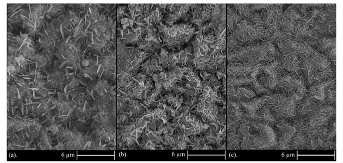
Figure 8. FESEM images of Zn-TiO2 nanocomposite coatings under constant current densities of 0.12 A/cm2 and particle concentrations in the electrolyte: (a) 5, (b) 10, and (c) 15 g/L.
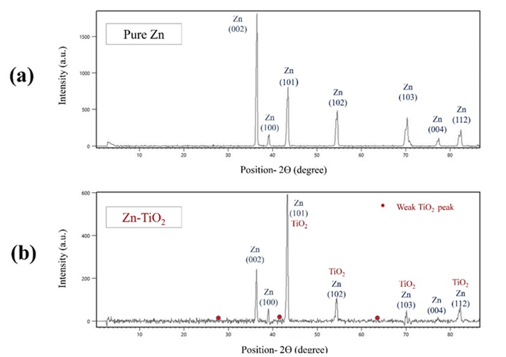
Figure 9. The XRD patterns of pure zinc and Zn-TiO2 nanocomposite coating electrodeposited at current density of 0.12 A/cm2, a) pure zinc and b) Zn-TiO2 (5 g/L).
According to the XRD patterns in Figure 9, the incorporation of TiO2 nanoparticles has played a significant role on the reduction of relative intensity of all characteristic peaks justifying that crystal growth on all crystallographic planes has been diminished. The decrease in peaks relative intensity and in consequence the crystal growth reduction which is also reported in other studies [54,55] is in consistence with our SEM studies in section 3.1, indicating the grain refinement and decrement in grain size.
The Weight Loss Measurements
The profiles of corrosion rate regarding pure zinc and Zn-TiO2 (5 g/L) nanocomposite coated specimens immersed in 3.5 wt.% NaCl solution for 216 hours were obtained, as depicted in Figure 10. The obtained findings exhibited the superior corrosion resistance of Zn-TiO2 nanocomposite coatings in comparison to that of the pure zinc coating. The amount of corrosion rate in Zn and Zn-TiO2 nanocomposite coatings was constant during the entire period of 9 days.
The results illustrated that the presence of TiO2 nanoparticles in zinc matrix, varies the corrosion behavior of zinc and the nanoparticles embedment leads to improvement of the corrosion resistance. Besides, the coating stability was intensified in corrosive environment. The addition of TiO2 nanoparticles in the electrodeposition process of zinc on the surface of low carbon steel substrate, significantly improves the corrosion resistance owing to the TiO2 role and the reinforcement effect of TiO2 nanoparticles in the nanocomposite coating.
Salt Spray Method (Salt Fog Testing)
Salt Spray technique is an industrial and also practical method for estimation of the service life of electroplated zinc deposits. In this test, the coated specimens were exposed to the vapors or fog of 5 wt.% NaCl solution. The fog or drops accumulate on the specimens’ surface and accelerates the corrosion. This results into appearance of zinc salts called white rust. Afterwards, the corrosion resistance of coated specimens was evaluated by the number of hours taken for the formation of white rust. The higher corrosion resistance leads to later production of white rust and thus the time for formation of corrosion products is increased. In this research, the pure zinc exhibited the white rust after 24 hours and Zn-TiO2 (5 g/L) nanocomposite after
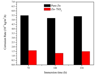
Figure 10. Variations of corrosion rate with immersion time for pure zinc coating and Zn-TiO2 nanocomposite coating (5 g/L) samples in 3.5 wt. % NaCl solution (specimens electrodeposited under the current density of 0.12 A/cm2).
72 hours (both specimens electrodeposited under the current density of 0.12 A/cm2). The results of this test prove the superior corrosion resistance of Zn-TiO2 nanocomposite coating with comparison to pure zinc coating under the specified mentioned conditions.
Electrochemical Measurements
Anodic Polarization Test
The anodic polarization measurements of pure zinc coating and Zn-TiO2 (deposited at the 5 g/L concentration of TiO2 nanoparticles) nanocomposite coating electrodeposited under the current density of 0.12 A/cm2 were measured in the salt solution with 3.5 wt. % NaCl and reported in the curve illustrated in Figure 11. Accordingly, the potential of Zn-TiO2 nanocomposite coating is more positive than that of pure Zn coating at all amounts of electric currents.
For nanocomposite coating, by increasing the current density, the anodic polarization potential is risen and moves toward the positive direction. Electrochemical results show that under mentioned conditions, Zn-TiO2 nanocomposite coating exhibits lower activity than that of pure Zn coating. Thus, they show better stability to the external environment. It should also be stated that by increasing the potential, the corrosion current values also increase. Likewise, the corrosion current value for the Zn-TiO2 nanocomposite coating is lower than that of pure zinc coating at the same potential.
The effect of nanoparticles participation in the coating on the corrosion resistance has been studied by different researchers. For instance, Shibli et al. [60] studied the high corrosion resistance of hot dip galvanic zinc reinforced with TiO2. Lei Shi et al. [61] also reported that the corrosion resistance was increased by the addition of SiC nanoparticles into the Ni-Co alloys. These results indicate that the corrosion resistance of nanocomposite coatings is highly related to the deposition parameters and also shape, size, and characteristics of co-deposited particles. Defects, cracks, gaps, crevices, and micro-holes are non-deniable on the metal surface. Nanoparticles are easily entered into these defects leading to change the corrosion mechanism from localized to more uniform type. In the present study, the defects are covered and filled by TiO2 nanoparticles on the zinc surface. Besides this, these micro-holes act as active sites for metal dissolution during the corrosion process. As a result, by covering these holes with TiO2 nanoparticles in the nanocomposite coating, it will cause a reduction in corrosion and dissolution of metal into a corrosive electrolyte.
Potentiodynamic Polarization Test
To have a deeper understanding of corrosion characteristic of pure zinc and Zn-TiO2 nanocomposite coatings, potentiodynamic polarization test was applied under the specific mentioned conditions. The important corrosion parameters like corrosion potential or Ecorr, corrosion current density or icorr , and anodic and cathodic Tafel constants (βa and βc) are extracted from potentiodynamic polarization curves and summarized in Table 3.
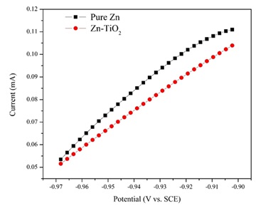
Figure 11. The anodic polarization curves for pure zinc coating and Zn-TiO2 (5 g/L) nanocomposite coating electrodeposited under the current density of 0.12 A/cm2 in NaCl solution (3.5 wt.%).
Table 3. Corrosion characteristics and TiO2 content of the coatings
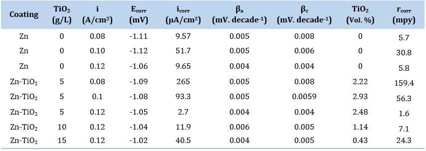
For pure zinc coatings, as shown in Table 3, by increasing the current density from 0.08 to 0.1 A/cm2, Ecorr (corrosion potential) is approximately constant and icorr (corrosion current density) is also increased. The rise in icorr is due to reduction in zinc crystallite size and also enhancement of the grain boundaries between these crystallites resulting in more exposed corrosion sites in the microstructure [53]. By increasing the current density from 0.1 to 0.12 A/cm2, icorr decreases which is in agreement with increase in Ecorr. The decrease in icorr or higher corrosion resistance in this range is mainly ascribed to the formation of a more uniform and compact microstructure (Figure 5) while the amount of grain boundaries between hexagonal zinc crystals is risen. As a result, it can be concluded that for analysis of icorr obtained for zinc deposited coatings, two main factors are of importance: (i) the amount of grain boundaries between hexagonal zinc crystals (if this overcomes, icorr is increased) and (ii) the amount of uniformity and compactness of surface morphology (if this overcomes, icorr is decreased).
For Zn-TiO2 nanocomposite coatings, as shown in Table 3, by rising the current density, icorr is steadily lowered indicating the improvement of corrosion resistance. The main point here is that by rising the electrodeposition current density from 0.08 to 0.1 A/cm2, the incorporation rate of TiO2 nanoparticles in the coating was enhanced and leads to improvement of corrosion resistance of composite coating. This behavior is the result of mechanism regarding corrosion improvement in composite coatings that occurs for two essential reasons:
- Participation of TiO2 nanoparticles into the zinc matrix results in the formation of several corrosion micro cells in which, inert TiO2 nanoparticles act as cathode and zinc matrix also acts as anode due to the higher electrochemical potential of TiO2 than zinc metal matrix. Thus, such corrosion micro cells accelerate the anode matrix polarization and result in the formation of passive sites.
- Inert TiO2 nanoparticles act as physical barriers to corrosion environment through microstructure modification. This occurs by filling the gaps and defects at the surface by TiO2 nanoparticles. As a matter of fact, in the presence of TiO2 nanoparticles, localized corrosion converts to uniform corrosion that is more predictable and possible to control [61,62].
For Zn-TiO2 nanocomposite coatings, by rising the current density from 0.1 A/cm2 to 0.12 A/cm2, although the amount of the TiO2 nanoparticles incorporated in the coating is lowered and as a result the corrosion resistance is improved. In other words, despite the decrease in the incorporated nanoparticles, rising the current density as a proportional factor with ions reduction rate or the driving force for movement of ions toward cathode, the corrosion resistance is risen owing to the formation of more uniform and compact microstructure. Therefore, two important factors have great influence on the corrosion characteristics of the nanocomposite coatings: (i) the incorporated rate of nanoparticles making the composite surface smoother and (ii) the level of electrodeposition current density affecting the uniformity and compactness of composite coatings.
For Zn-TiO2 nanocomposite coatings, according to Table 3, the corrosion current density (icorr) was recorded to be lower than the pure Zn coating deposited under the 5 g/L concentration of TiO2 nanoparticles. By increasing the concentration of TiO2 nanoparticles in the electrolyte from 5 to 15 g/L, icorr was significantly increased. In fact, at constant current density, icorr was highly relied on the function of incorporated particle content in the coating. Thus, according to the further reduction in participation rate of TiO2 nanoparticles under the 10 and 15 g/L concentration of TiO2 nanoparticles, the corrosion resistance was steadily lowered than that of the sample deposited at concentration of 5 g/L in the same condition of deposition.
This increased distribution of nanoparticles and coating uniformity is also observed in FESEM images illustrated in Figure 8. Accordingly, by increasing the particle concentration in the electrolyte, the distribution of nanoparticles and uniformity of the coating has risen, and also resulted in formation of a more uniform microstructure and a greater number of flakes of smaller size.
By assessing the data reported in Table 3, for several conditions, icorr is higher for Zn-TiO2 nanocomposite coating with respect to that of the pure Zn coating. This clearly indicates the electrodeposition of nanocomposite coatings with reinforced particles, in this case for TiO2 nanoparticles, will not necessarily increase the corrosion resistance. The rise or fall of corrosion resistance is highly relied on the influence (e.g., amount and distribution) of incorporated particle into the matrix. In case of zinc metal matrix coatings, as mentioned previously, the zinc morphology can alter drastically from hexagonal platelet to flake type grain microstructure after incorporation of TiO2 nanoparticles.
As demonstrated in Figures 6 to 8, the morphology of electrodeposited Zn-TiO2 nanocomposite coatings are almost flake type grains. This type of morphology is the result of significant grain refinement and possess much higher grain boundaries than hexagonal platelet microstructure which is more observed in pure zinc coatings. This presence of higher amount of grain boundaries makes the coating more susceptible to corrosion.
It is eventually observed that between all pure and composite deposited coatings (see Table. 3), the electrodeposited Zn-TiO2 (5 g/L) coating at the current density 0.12 A/cm2 exhibited the lowest amount of icorr (equals to highest corrosion resistance) of 2.7 µA/cm2 equals to 1.6 mpy. It is noteworthy that in this study, the electrodeposited Zn-TiO2 (5 g/L) coating at the current density 0.12 A/cm2 has the highest corrosion resistance between all pure and composite deposited coatings. In case of industrial applications of zinc-based coatings, the lowest icorr is not always the best choice for application of a specific coating, since the protection mechanism of zinc is acting as a sacrificial coating and should be corroded in order to protect its substrate from corrosive environment. Thus, in case of industrial applications of zinc-based coatings, the choice of coating between various deposition parameters depends on the different parameters like desired lifetime and the constituents of corrosive media.
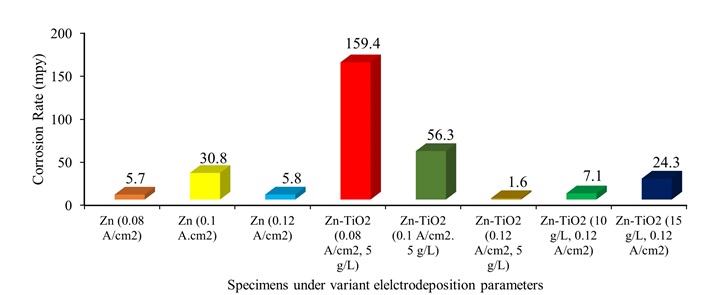
Figure 12. Corrosion rates (mpy) of the pure zinc and Zn-TiO2 nanocomposite coatings under variant electrodeposition current density and TiO2 nanoparticle concentration.
The corrosion rates (C.R) versus mpy for pure Zn and Zn-TiO2 nanocomposite coatings were calculated by following equation:
Corrosion Rate (mpy) = 0.13 (1)
Where, M (g) describes molar mass, n denotes the charge number, and d (g/cm3) indicates the density of zinc. The values of the corrosion rates of the pure Zn and Zn-TiO2 nanocomposite coating specimens are calculated and illustrated in Figure 12.
Morphology after Corrosion
To have a full assessment of coatings morphology, the pure zinc and Zn-TiO2 (5 g/L) coated specimens electrodeposited under the current density of 0.12 A/cm2 were subjected into the chemical corrosion process in 3.5 wt.% NaCl solution for 9 days. The corroded samples were used to take FESEM images as indicated in Figures 13 and 14. The FESEM images of the corroded specimens demonstrates the less corrosion resistance of pure zinc coating than that of the corroded Zn-TiO2 nanocomposite coating.
It is also obvious that in the mentioned conditions, nanocomposite coating exhibits more uniform corrosion whereas pure zinc coating exhibits more localized corrosion. In case of nanocomposite coating, the corrosion product sites have a smaller size than that of pure zinc coating.
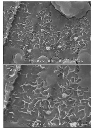
Figure 13. FESEM images for pure zinc coating specimens (electrodeposited under the current density of 0.12 A/cm2) after 9 days weight loss measurements at two different magnifications.
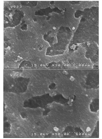
Figure 14. FESEM images for Zn-TiO2 (5 g/L) nanocomposite coating specimens (electrodeposited under the current density of 0.12 A/cm2) after 9 days weight loss measurements at two different magnifications.
This shows the higher rate of corrosion in the pure zinc coating than Zn-TiO2 nanocomposite coating, and also validates the former corrosion resistance measurements. The FESEM studies further confirms the obtained results of the weight loss and polarization tests.
Conclusion
In this research, Zn and Zn-TiO2 nanocomposite coatings were successfully prepared by electro-codeposition method. The TiO2 nanoparticles were dispersed uniformly in the solution and included in the zinc coating during electrodeposition. The incorporation of TiO2 nanoparticles in the coating resulted into reduction of the crystal size and also until a critical concentration, led to remarkable improvement of the corrosion resistance regarding the nanocomposite coatings compared to that of the pure zinc coating. The rise of corrosion resistance is originated from the physical barrier produced by TiO2 against the corrosion process through filling crevices, gaps and micro holes on the surface of zinc coating. The uniformly distributed TiO2 nanoparticles, until the critical concentration, resulted into the increment of the corrosion potential value toward the more positive values for Zn-TiO2 nanocomposite coating and in consequence higher corrosion resistance. The nanocomposite coatings depicted more uniform corrosion.
In this study, the use of TiO2 nanoparticles has been investigated to control of zinc coating corrosion, and also the electrolyte could generate Zn-TiO2 nano composite coatings at larger scales.
Increase in the electrodeposition current density from 0.08 to 0.12 A/cm2 for both pure Zn and Zn-TiO2 nanocomposite coatings, led to higher nucleation rate, reduction rate of ions, and also reduction in crystal growth was occurred which subsequently led to deposit more and smaller crystals. By participation of TiO2 nanoparticles in the coating, the morphology was changed drastically from hexagonal platelet crystals to flake type grains causing remarkable grain refinement and reduction in crystal growth observed by FESEM and confirmed by XRD.
Due to the further rising of TiO2 nanoparticles concentration from 5 to 15 g/L, the incorporation rate of TiO2 nanoparticles had gradually decreased, and grain refinement associated with more uniform surface was observed at 15 g/L TiO2 concentration. Weight loss measurements, salt spray tests, and anodic polarization test indicated the higher corrosion resistance of Zn-TiO2 (5 g/L) than that of the pure Zn coating electrodeposited under the current density of 0.12 A/cm2. Potentiodynamic polarization results showed that rising the current density from 0.08 to 0.1 A/cm2, icorr was increased for pure zinc coating, then a decrease from 0.1 to 0.12 A/cm2 occurred. However, for Zn-TiO2 coating by increase in current density from 0.08 to 0.12 A/cm2, a steadily decrease of icorr was observed. Furthermore, through furthering the TiO2 nanoparticles concentration from 5 to 15 g/L, a significant steadily enhancement was observed in icorr owing to the noticeable reduction in incorporation rate.
To sum up, the best corrosion resistance among all investigated pure and composite deposited coatings was reported to be for the electrodeposited Zn-TiO2 (5 g/L) coating under the current density 0.12 A/cm2 showing the lowest amount of icorr of 2.7 µA/cm2 equals to 1.6 mpy.
Disclosure statement
The authors declare that they have no conflict of interest.
Orcid
Mohammad Sajjadnejad : 0000-0001-5112-1791
Seyed Mohammad Saleh Haghshenas : 0000-0001-5878-8214
)